Kidsblock tutorial
1. Getting started with Kidsblock software
1. Instruction:
The Kidsblock, based on the Scratch graphical programming software, integrates multiple mainstream mainboards, sensors as well as modules. It can be programmed by dragging graphical blocks and using the C/C++ programming language, making programming easy and interesting for children to learn.
2. Download and install KidsBlock software
Install Development Board Driver
How to install development board driver
Start your first program Quick Start
3. Interface Setting:
After the KidsBlock is installed,open KidsBlock to click <“Beetlebot”<“Connect”,
Then the Beetlebot is connected. Click “Go to Editor” to return the code editor.
will change into and
and into
into .
.
This means the Beetlebot is connected to the COM port.


If the Beetlebot is connected, butdoesn’t change into.
Just clickto connect the COM port.Click,then click“Connect”,after a while, if the“Connected”page pops up,the com port will be connected.


Then click  to switch the mode, the modewill switch to


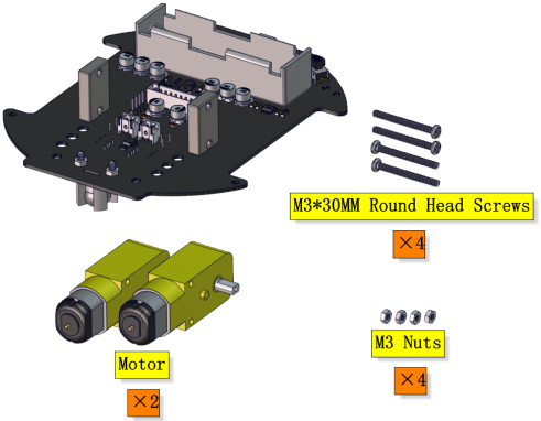
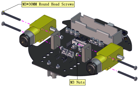
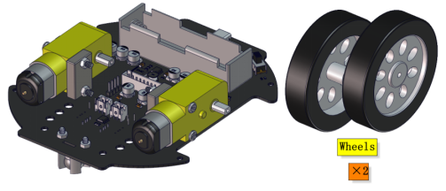
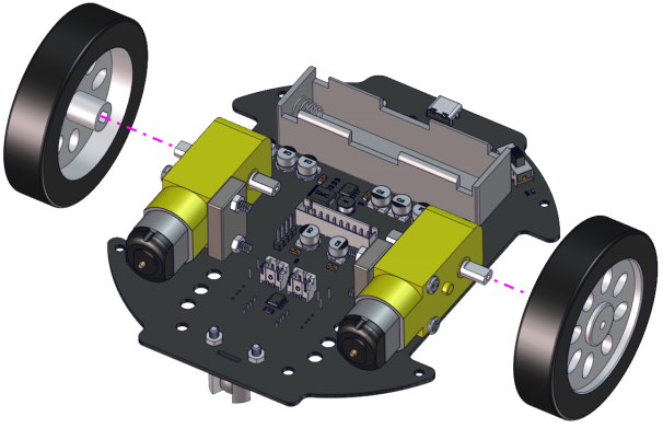
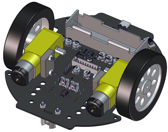
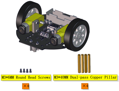
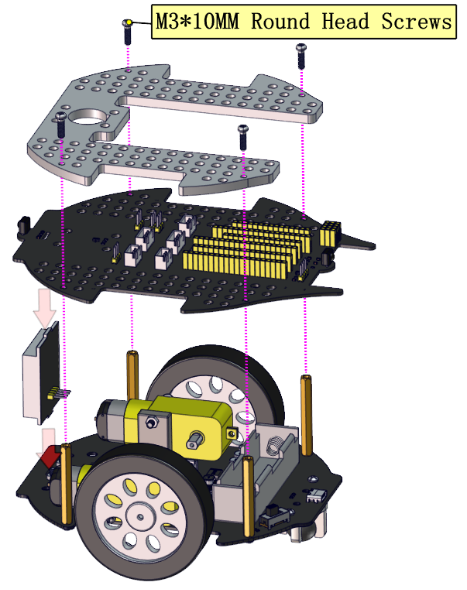
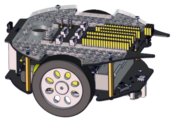
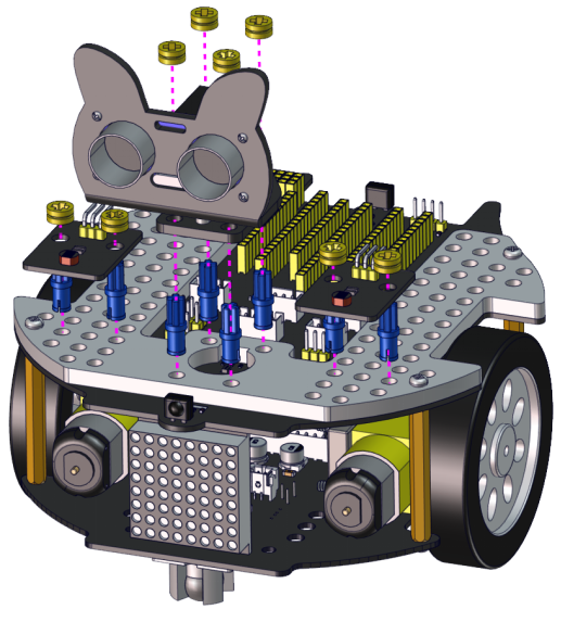
2. Assemble Beetlebot Robot
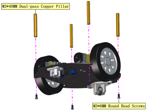
Step 1
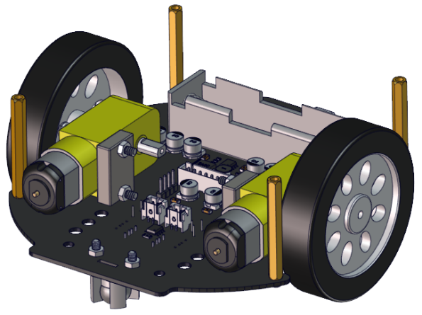
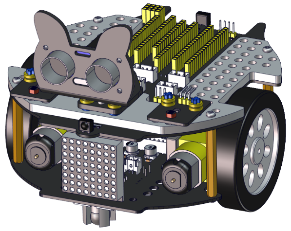
Step 2
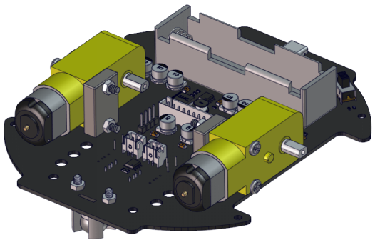
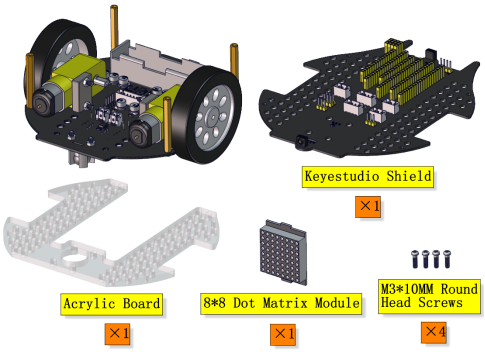
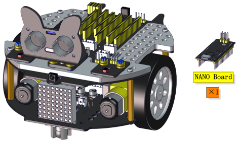
Step 3
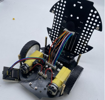
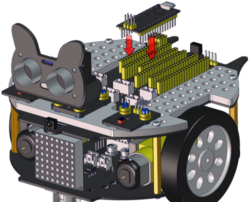
Step 4
Step 5
Left Motor |
Right Motor |
|---|---|
L |
R |

8*8 Dot Matrix Display |
PCB |
|---|---|
G |
G |
5V |
5V |
SDA |
SDA |
SCL |
SCL |
Step 6
Step 7
Step 8
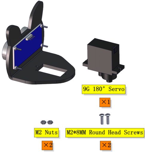
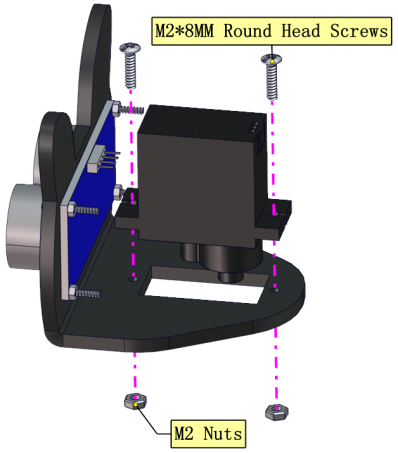
Step 9
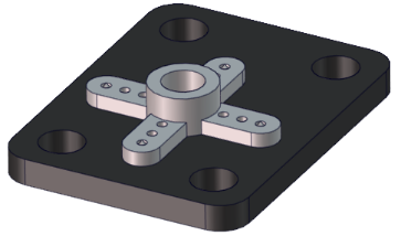
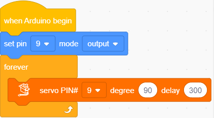
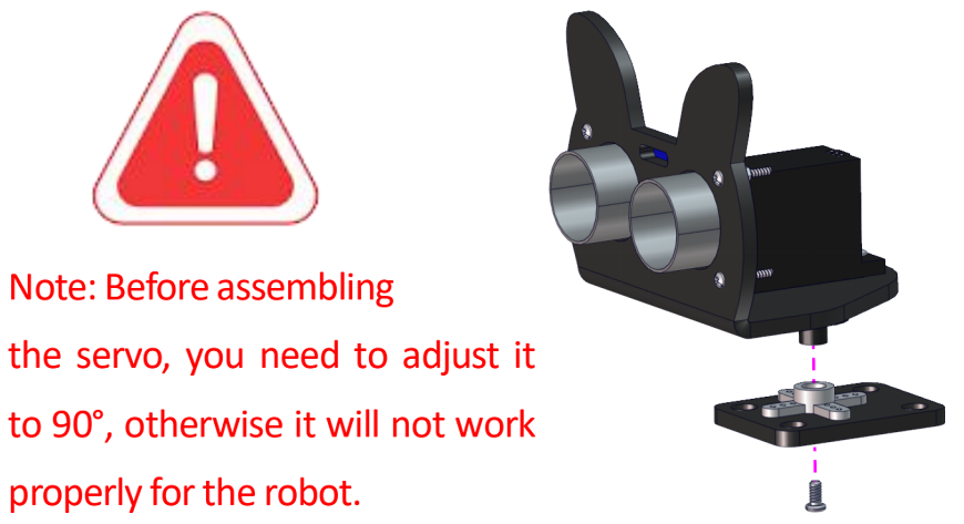
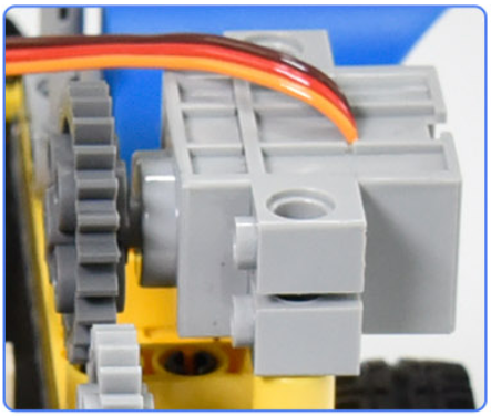
Adjust the angle of the servo to 90 degree.
Servo |
PCB |
|---|---|
Brown line |
G |
Red line |
5V |
Orange line |
S1(D9) |
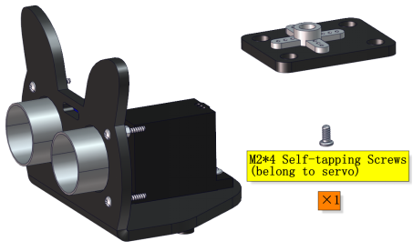
Writing the following code in kidsBlock software and upload it to the motherboard, or just open the code provided by us and upload it to the motherboard.
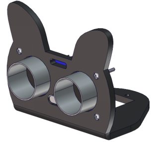
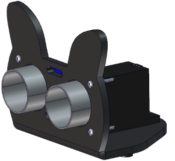
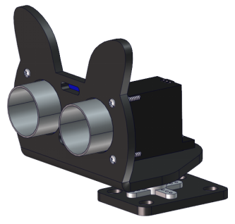
Keep the ultrasonic sensor parallel to the board
Step 10
Step 11
Step 12
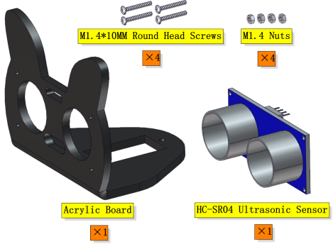
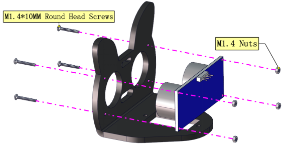
Wire up the ultrasonic sensor
Ultrasonic Sensor |
PCB |
|---|---|
Vcc |
5V |
Trig |
S2(D8) |
Echo |
S1(D7) |
Gnd |
G |
Wire up the servo
Servo |
PCB |
|---|---|
Brown line |
G |
Red line |
5V |
Orange line |
S1(D9) |
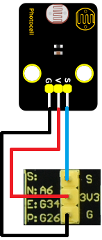
Wire up the left photoresistor
Left photoresistor |
PCB |
|---|---|
G |
G |
V |
V |
S |
S(A6) |
Wire up the right photoresistor
Right photoresistor |
PCB |
|---|---|
G |
G |
V |
V |
S |
S(A7) |
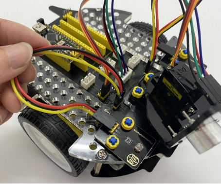
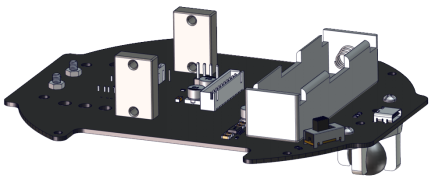
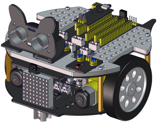
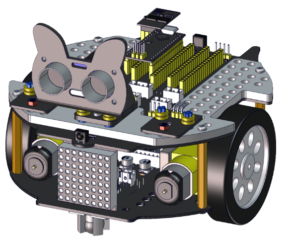
Beetle Robot Car
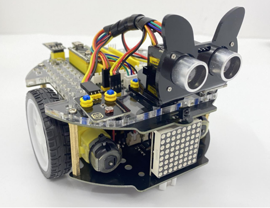
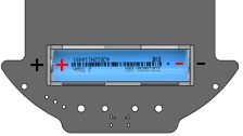
We adopt a model 18650 lithium battery with a pointed positive pole, whose power and capacity are not required.
3. Projects:
Project 1: LED Blinking
(1)Description:
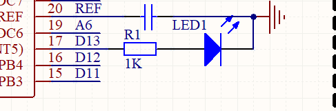
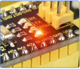
There is an onboard LED (L) on our Arduino Nano board connected to D13. In this experiment, we WILL make this LED blink.
LED blinking is the most basic experimental project for Arduino enthusiasts. Let’s get started.
(2)Components Required:
(3)Knowledge:
On-board LED:
LED, the abbreviation of light emitting diodes, consists of Ga, As, P, N chemical compounds and so on. It is easy to control through the IO port(D13) of the Arduino Nano board.
(4)Test Code

(5)Test Result:
Upload the test code to the Arduino Nano board and power up with a USB cable. Then the on-board LED will flash.
Project 2: 6812 RGB
(1)Description:
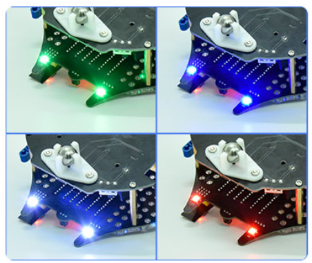
There are 4 RGB LEDs can be widely used in the decoration of buildings, bridges, roads, gardens, courtyards and so on by colors adjustment.
In this experiment, we will demonstrate different lighting effects with them.
(2)Components Required:
(3)Component Knowledge
SK6812RGB:
From the schematic diagram, we can see that these four pixel lighting beads are all connected in series. In fact, no matter how many they are, we can use a pin to control a light and let it display any color. The pixel point contains a data latch signal shaping amplifier drive circuit, a high-precision internal oscillator and a 12V high-voltage programmable constant current control part, which effectively ensures the color of the pixel point light is highly consistent.
The data protocol adopts a single-wire zero-code communication method. After the pixel is powered up and reset, the S terminal receives the data transmitted from the controller. The first 24bit data sent is extracted by the first pixel and sent to the data latch of the pixel.

(4)Test Code:
The SK6812RGB on the PCB board is controlled by the IO port (A3).

(5)Test Result:
Upload the test code to the Arduino Nano board and power up by a USB cable. Then the four RGB lights on the PCB demonstrate multi-color light effect.
Project 3: Play Music
(1)Description:
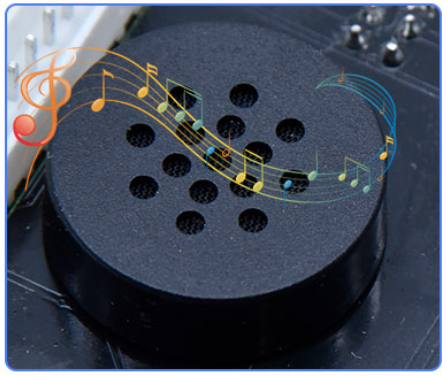
There is a power amplifier component on the expansion board, which is often used to play music and serve as an external amplifying device for music playback devices.
In this experiment, we use the speaker amplifier component to play music.
(2)Components Required:
(3)Knowledge:
Power amplifier modules(equivalent to a passive buzzer) don’t have internal oscillation circuits.
The power amplifier module can chime sounds with different frequency when power it up.
(4)Test Code:
The speaker component on the PCB board is controlled by the D3 of the Arduino Nano board.

(5)Test Result:
Upload the test code to the Arduino Nano board and power up with a USB cable. Then the power amplifier component will play music.
Project 4: 8*8 Dot Matrix
(1)Description:
Composed of LED emitting tube diodes, the 8*8 LED dot matrix are applied widely to public information display like advertisement screen and bulletin board, by controlling LED to show words, pictures and videos, etc.
(2)Components Required:
(3)Knowledge:
There are different types of matrices, including 4×4, 8×8 and 16×16 and etc. It contains 64 LEDs.
The inner structure of 8×8 dot matrix is shown below.
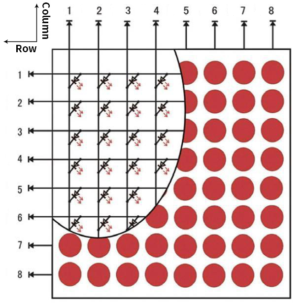
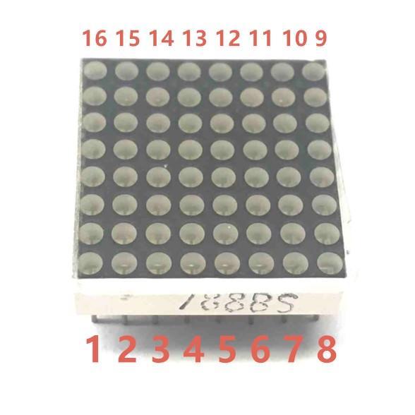
Every LED is installed on the cross point of row line and column line. When the voltage on a row line increases, and the voltage on the column line reduces, the LED on the cross point will light up. 8×8 dot matrix has 16 pins. Put the silk-screened side down and the numbers are 1, 8, 9 and 16 in anticlockwise order as marked below.
The definition inner pins are shown below:
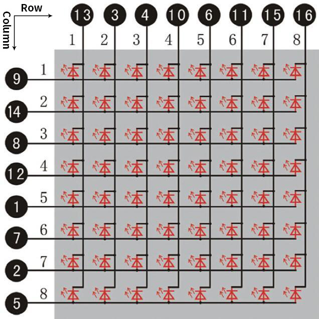
For instance, to light up the LED on row 1 and column 1, you should increase the voltage of pin 9 and reduce the voltage of pin 13.
HT16K33 8X8 Dot Matrix
The HT16K33 is a memory mapping and multi-purpose LED controller driver. The max. Display segment numbers in the device is 128 patterns (16 segments and 8 commons) with a 13*3 (MAX.) matrix key scan circuit. The software configuration features of the HT16K33 makes it suitable for multiple LED applications including LED modules and display subsystems. The HT16K33 is compatible with most microcontrollers and communicates via a two-line bidirectional I2C-bus.
The picture below is the working schematic of HT16K33 chip:

We design the drive module of 8*8 dot matrix based on the above principle. We could control the dot matrix by I2C communication and two pins of microcontroller, according to the above diagram.
Specification:
Input voltage: 5V
Rated input frequency: 400KHZ
Input power: 2.5W
Input current: 500mA
Introduction for Modulus Tool
The online version of dot matrix modulus tool:http://dotmatrixtool.com/#
①Open the link to enter the following page.

②The dot matrix is 8*8 in this project. So set the height to 8, width to 8; as shown below.

③Click Byte order to select Row major.

④ Generate hexadecimal data from the pattern.
As shown below, the left button of the mouse is for selection while the right is for canceling. Thus you could use them to draw the pattern you want, then click Generate to yield the hexadecimal data needed.

The generated hexadecimal code(0x00, 0x66, 0x00, 0x00, 0x18, 0x42, 0x3c, 0x00) is what will be displayed, so you need to save it for next procedure.
(4)Wiring up:
8*8 Dot matrix display |
PCB Board |
|---|---|
G |
G |
5V |
5V |
SDA |
SDA |
SCL |
SCL |
(5)Test Code:
The 8*8 dot matrix is controlled by A4(SDA)and A5(SCL)of the Arduino Nano board.

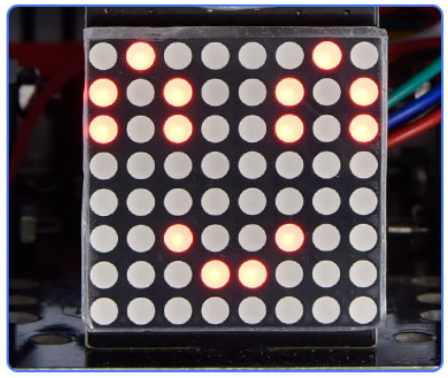
(6)Test Result:
Upload the test code to the Arduino Nano board and power up by a USB cable, the 8*8 dot matrix display will show show patterns.
Project 5: Servo Rotation
(1)Description:
There are two servos on the car. We take the servo connected to pin D9 as an example.
The servo is a motor that can rotate very accurately. It has been widely applied to toy cars, remote control helicopters, airplanes, robots and other fields. In this project, we will use the Nano motherboard to control the servo to spin.
(2)Components Required:
(3)Knowledge:

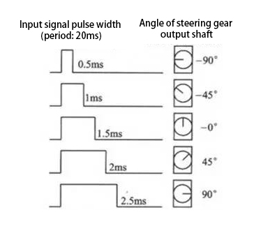
Servo motor is a position control rotary actuator. It mainly consists of a housing, a circuit board, a core-less motor, a gear and a position sensor. Its working principle is that the servo receives the signal sent by MCU or receiver and produces a reference signal with a period of 20ms and width of 1.5ms, then compares the acquired DC bias voltage to the voltage of the potentiometer and obtain the voltage difference output.
When the motor speed is constant, the potentiometer is driven to rotate through the cascade reduction gear, which leads that the voltage difference is 0, and the motor stops rotating. Generally, the angle range of servo rotation is 0°–180 °.
The rotation angle of servo motor is controlled by regulating the duty cycle of PWM (Pulse-Width Modulation) signal. The standard cycle of PWM signal is 20ms(50Hz). Theoretically, the width is distributed between 1ms-2ms, but in fact, it’s between 0.5ms-2.5ms. The width corresponds the rotation angle from 0° to 180°. But note that for different brand motors, the same signal may have different rotation angles.
In general, servo has three lines in brown, red and orange. The brown wire is grounded, the red one is a positive pole line and the orange one is a signal line.

(4)Wire up:
Servo |
PCB Board |
|---|---|
Brown |
G |
Red |
5V |
Orange |
S1(D9) |
(5)Test Code:
The servo for controlling the ultrasonic sensor is controlled by the D9 of the Arduino Nano board.

(6)Test Result:
Upload the test code to the Arduino Nano board, and power up with a USB cable. Then the arm of the servo will rotate to 0°, 45°, 90°, 135° and 180°.
Project 6: Motor Driving and Speed Control
(1)Description:
There are many ways to drive motors. This car uses the most commonly used DRV8833 motor driver chip, which provides a dual-channel bridge electric driver for toys, printers and other motor integration applications.
In this experiment, we use the DRV8833 motor driver chip on the expansion board to drive the two DC motors, and demonstrate the effect of forward, backward, left-turning, and right-turning.
(2)Components Required:
(3)Knowledge:
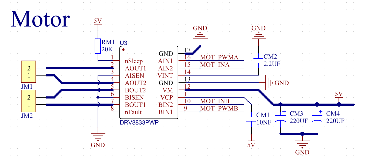
DRV8833 motor driver chip: Dual H-bridge motor driver with current control function, can drive two DC motors, one bipolar stepper motor, solenoid valve or other inductive loads. Each H-bridge includes circuitry to regulate or limit winding current.
An internal shutdown function with a fault output pin is used for over-current and short circuit protection, under-voltage lockout and over-temperature. A low-power sleep mode is also added. Let’s take a look at the schematic diagram of the DRV8833 motor driver chip driving two DC motors:

If you want to get insight to it, you can check the specification of this chip. Just browse it in the“Attachments”folder.

(4)Specification:
Input voltage of logic part: DC 5V
Input voltage of driving part : DC 5V
Working current of logic part: <30mA
Operating current of driving part: <2A
Maximum power dissipation: 10W (T=80℃)
Motor speed: 5V 200 rpm / min
Motor drive form: dual H-bridge drive
Control signal input level: high level 2.3V<Vin<5V, low level -0.3V<Vin<1.5V
Working temperature: -25~130℃
(5)Drive the car to move
From the above diagram, the direction pin of the left motor is D4; the speed pin is D6; D2 is the direction pin of the right motor; and D5 is speed pin.
PWM drives the robot car. The PWM value is in the range of 0-255. The more the PWM value is set, the faster the rotation of the motor.
Function |
D4 |
D6(PWM) |
Left motor |
D2 |
D5(PWM) |
Right motor |
|---|---|---|---|---|---|---|
forward |
LOW |
200 |
clockwise |
LOW |
200 |
clockwise |
Go back |
HIGH |
50 |
anticlockwise |
HIGH |
50 |
anticlockwise |
Turn left |
HIGH |
200 |
anticlockwise |
LOW |
200 |
clockwise |
Turn right |
LOW |
200 |
clockwise |
HIGH |
200 |
anticlockwise |
Stop |
LOW |
0 |
stop |
LOW |
0 |
stop |
(6)Test Code:

(7)Test Result:
Upload the test code to the Arduino Nano board, install batteries, turn the power switch to ON end and power up. The car moves forward for 2s, back for 2s, turn left for 2s, right for 2s and stops for 2s.
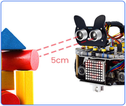
Project 7: Ultrasonic Sensor
There is an ultrasonic sensor on the car. It is a very affordable distance-measuring sensor.
The ultrasonic sensor sends a high-frequency ultrasonic signal that human hearing can’t hear. When encountering obstacles, these signals will be reflected back immediately. After receiving the returned information, the distance between the sensor and the obstacle will be calculated by judging the time difference between the transmitted signal and the received signal. It is mainly used for object avoidance and ranging in various robotics projects.
Project 7.1: Ultrasonic Ranging
(1)Description:
In this experiment, we use an ultrasonic sensor to measure distance and print the data on a serial monitor.
(2)Components Required:
(3)Knowledge:
The HC-SR04 ultrasonic sensor uses sonar to determine distance to an object like what bats do. It offers excellent non-contact range detection with high accuracy and stable readings in an easy-to-use package. It comes complete with ultrasonic transmitter and receiver modules.
The HC-SR04 or the ultrasonic sensor is being used in a wide range of electronics projects for creating obstacle detection and distance measuring application as well as various other applications. Here we have brought the simple method to measure the distance with Arduino and ultrasonic sensor and how to use ultrasonic sensor with Arduino.

Use method and timing chart of ultrasonic module:
Setting the delay time of Trig pin of SR04 to 10μs at least, which can trigger it to detect distance.
After triggering, the module will automatically send eight 40KHz ultrasonic pulses and detect whether there is a signal return. This step will be completed automatically by the module.
If the signal returns, the Echo pin will output a high level, and the duration of the high level is the time from the transmission of the ultrasonic wave to the return.

Time=Echo pulse width, unit: us
Distance(cm)=time/ 58
Distance(inch)=time/ 148

The HC-SR04 ultrasonic sensor has four pins: Vcc, Trig, Echo and GND.
The Vcc pin provides power generating ultrasonic pulses and is connected to Vcc/+5V. The GND pin is grounded/GND.
The Trig pin is where the Arduino sends a signal to start the ultrasonic pulse. The Echo pin is where the ultrasonic sensor sends information about the duration of the ultrasonic pulse stroke to the Arduino control board.
(4)Wiring Up
Ultrasonic Sensor |
PCB Board |
|---|---|
Vcc |
5V |
Trig |
S2(D8) |
Echo |
S1(D7) |
Gnd |
G |
(5)Test Code:
The pin Trig and Echo of the ultrasonic sensor are controlled by the D8 and D7 of the Arduino Nano.

(6)Test Result:
Upload the test code to the Arduino Nano board, power up with a USB cable, open the serial monitor to click  and set baud rate to 9600.
When you move an object in front of the ultrasonic sensor, it will detect the distance and the serial monitor will show the distance value.

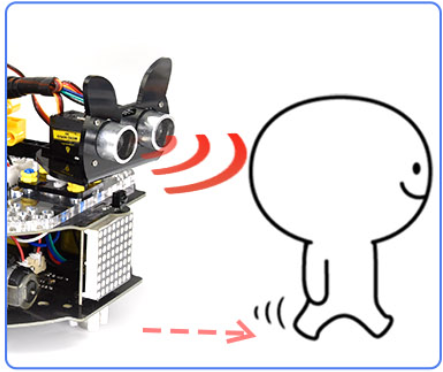
Project 7.2: Ultrasonic Following
(1)Description:
In the above experiments, we have learned about the 8*8 dot matrix, motor drivers and speed regulation, ultrasonic sensors, servos and other hardware. In this experiment, we will combine them to create a follow car with the ultrasonic sensor. The can can follow an object to move through measuring distance.
(2)Components Required:
(3)Working Principle:
Detection |
Detect the front distance Distance(unit:cm) |
|---|---|
Condition 1 |
Distance<8 |
State |
Go back(set PWM to 100) |
Condition 2 |
8≤distance<13 |
State |
stop |
Condition 3 |
13≤distance<35 |
State |
Go forward(set PWM to 100) |
Condition 4 |
distance≥35 |
State |
stop |
(4)Flow Chart:

(5)Test Code:

(6)Test Result:
Upload the code to the Arduino Nano board, install batteries and turn the switch to the ON end and power up. Then the car will follow the obstacle to move.
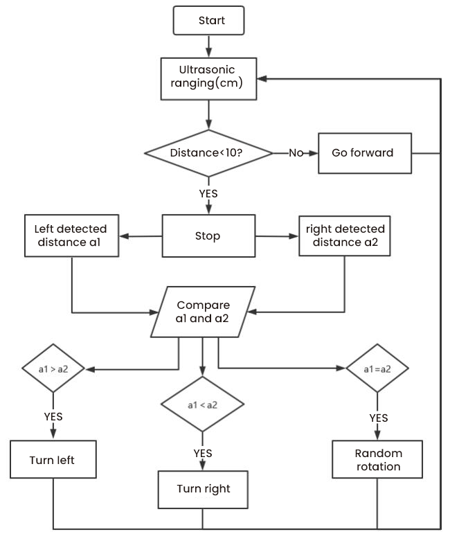
Project 7.3: Dodge obstacles
(1)Description:
In this project, we will take advantage of the ultrasonic sensor to detect the distance away from the obstacle so as to avoid them.
(2)Components Required:
(3)Working Principle:


(4)Flow Chart:
(5)Test Code:

(6)Test Result:
Upload the test code to the Arduino Nano board, put batteries in the battery holder, turn the power switch to the ON end and power up. Then the car can automatically dodge obstacles.
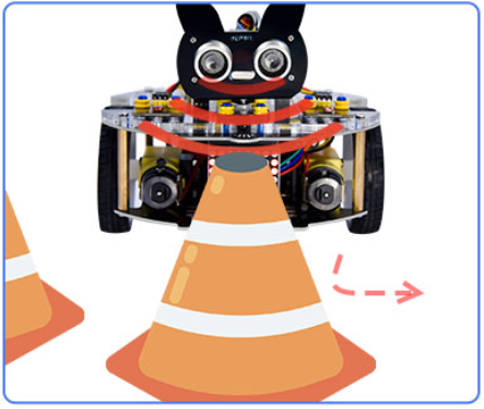
Project 8: Line Tracking Sensor
There are two IR line tracking sensors on the car. They are actually two pairs of ST188L3 infrared tubes and used to detect black and white lines. In this project, we will make a line tracking car.
Project 8.1: Reading Values
(1)Description:
In this experiment, we use ST188L3 infrared tubes to detect black and white lines, then print the data on the serial monitor.
(2)Components Required:
(3)Knowledge:
Infrared line tracking:
The IR line tracking sensor boasts a pair of ST188L3 infrared tubes. ST188L3 tubes has an infrared emitting diode and a receiver tube. When the emitting diode emits an infrared signal then received by the receiving tube after being reflected by the white object. Once the receiving tube receives the signal, the output terminal will output a low level (0); when the infrared emitting diode emits an infrared signal, and the infrared signal is absorbed by the black object, a high level (1) will be output, thus realizing the function of detecting signals through infrared rays.
Warning: Reflective optical sensors (including IR line tracking sensors) shouldn’t be applied under sunlight as there is a lot of invisible light such as infrared and ultraviolet.
Values detected by the line tracking sensor are shown in the table.
The value will be 1 if detecting black or no objects and the value 0 will appear if detecting white objects.
The detected black object or no object represents 1, and the detected white object represents 0.
Left |
Right |
Value(Binary ) |
|---|---|---|
0 |
0 |
00 |
0 |
1 |
01 |
1 |
0 |
10 |
1 |
1 |
11 |
(4)Test Code:
The line tracking sensors of the PCB board are controlled by D11 and D10 of the Arduino Nano baord.

(5)Test Result:
Upload the test code to the Arduino Nano board, power up with a USB cable, open the serial monitor to click and
set baud rate to 9600.
Put a black thing under the line tracking sensor of the car and move it, you will see different indicators light up, and at the same time you will see the value on the serial monitor.
The sensitivity can be adjusted by rotating the potentiometer. When the indicator light is adjusted to the critical point of on and off state, the sensitivity is the highest.

Project 8.2: Line Tracking
(1)Description:
We’ve introduced the knowledge of motor drivers, speed regulation, and infrared line tracking. In this experiment, the car will perform different actions according to the values transmitted by the infrared tracking.
(2)Components Required:
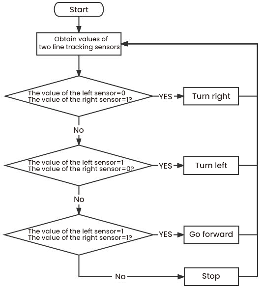
(3)Working Principle:
Left |
Right |
Value(Binary ) |
State |
|---|---|---|---|
0 |
0 |
00 |
Stop |
0 |
1 |
01 |
Turn right |
1 |
0 |
10 |
Turn left |
1 |
1 |
11 |
Move forward |
(4)Flow Chart:
(5)Test Code:

(6)Test Result:
Upload the test code to the Arduino Nano board, turn the power switch to the ON end, power up and put the car on a map we provide. Then it will perform different functions via values sent by line tracking sensors.
Project 9: Light Following
There are two photoresistors on the car. They can vary with the light intensity and send information to the Nano board to control the car.
Photoresistors can determine and conduct the car to move by detecting light.
Project 9.1: Read Values
(1)Description:
In this experiment, we will learn the working principle of the photoresistor.
(2)Components Required:
(3)Knowledge:
Photoresistor:
It mainly uses a photosensitive resistance element whose resistance varies from the light intensity. The signal terminal of the sensor is connected to the analog port of the microcontroller. When the light is stronger, the analog value at the analog port will increase; on the contrary, when the light intensity is weaker, the analog value of the microcontroller will reduce. In this way, the corresponding analog value can reflect the ambient light intensity.
(4)Wire up:
Through the wiring-up diagram, signal pins of two photoresistors are connected to A6 and A7 of the Nano board.
For the following experiment, we use the photoresistor connected to A6 to finish experiments. First, let’s read analog values.
Left photoresistor |
PCB board |
|---|---|
G |
G |
V |
V |
S |
S(A6) |
(5)Test Code:
The left photoresistor is controlled by the A6 of the Arduino Nano board.

(6)Test Result:
Upload the test code to the Arduino Nano board, power up with a USB cable, open the serial monitor to click and
set baud to 9600.
When the light intensifies, the analog value will get increased; on the contrary, the analog value will get reduced.

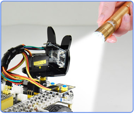
Project 9.2: Light Following Car
(1)Description:
We have learned the working principle of photoresistor, motor and speed regulation. In this experiment, we will use a photoresistor to detect the intensity of light as as to achieve the light following effect.
(2)Components Required:
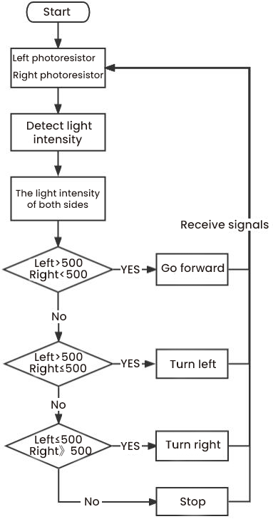
(3)Working Principle:
Analog value of the left sensor |
Analog value of the right sensor |
Function |
|---|---|---|
>500 |
>500 |
Move forward |
>500 |
≤500 |
Move to left |
≤500 |
>500 |
Move to right |
<500 |
<500 |
Stop |
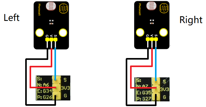
(4)Wiring up:
Left Photoresistor |
PCB Board |
Right photoresistor |
PCB Board |
|
|---|---|---|---|---|
G |
G |
G |
G |
|
V |
V |
V |
V |
|
S |
S(A6) |
S |
S(A7) |
(5)Flow Chart:
(6)Test Code:
The left and right photoresistors are controlled by A6 and A7 of the Arduino Nano board.

(7)Test Result:
Upload the test code to the Arduino Nano board, put batteries in the battery holder, turn the power switch to the ON end and power up. Then the car will follow the light to move.
Project 10: IR Remote Control
Infrared remote controls are everywhere in daily life. It is used to control various home appliances, such as TV, speakers, video recorders and satellite signal receivers.
The remote control is composed of an IR emitter, an IR receiver and a decoding MCU. In this project, we will make a IR remote control car.
Project 10.1: IR Remote and Reception
(1)Description:
In this experiment, we will combine the IR receiver and the IR remote control to read key values and show them on the serial monitor.
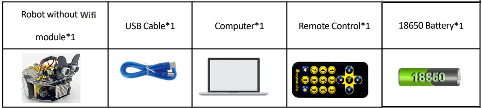
(2)Components Required:
(3)Knowledge:
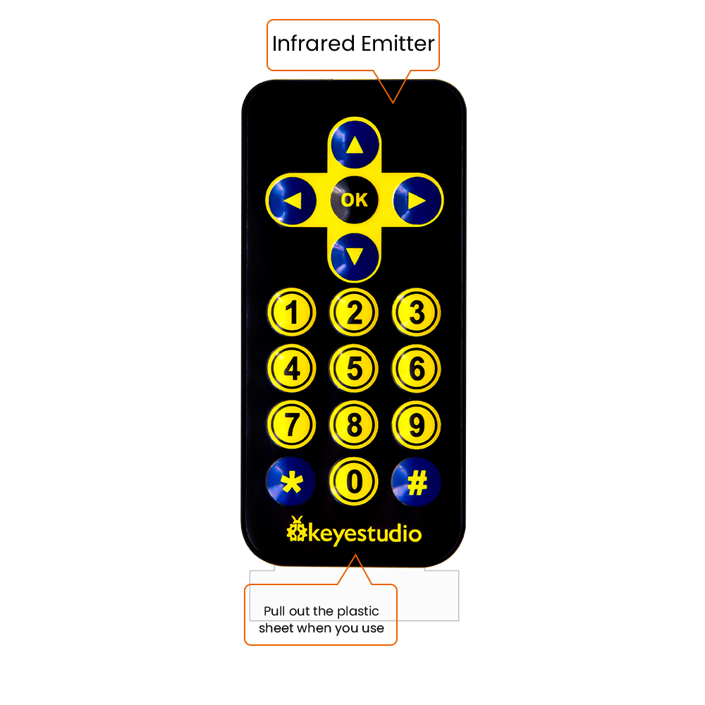
IR Remote Control:
It is a device with buttons. When the key is pressed, IR signals will be sent.
Infrared remote control technology is widely used, such as TVs, air conditioners and so on. And it can control air conditioners and TVs.
The infrared remote control adopts NEC coding, and the signal period is 110ms.
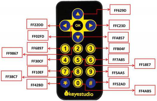
The remote control is shown below:
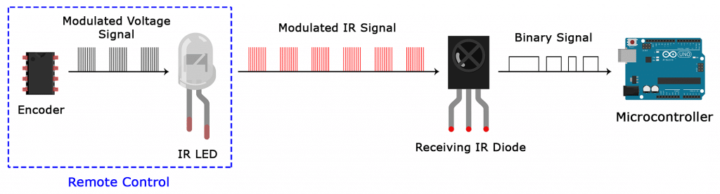
Infrared (IR) receiver:
It can receive infrared light and be used to detect the infrared signal emitted by the infrared remote control.
It can demodulate the received infrared light signal and convert it back to binary, and then transmit the information to the microcontroller.
NEC Infrared communication protocol:
NEC Protocol
To my knowledge the protocol I describe here was developed by NEC (Now Renesas). I’ve seen very similar protocol descriptions on the internet, and there the protocol is called Japanese Format.
I do admit that I don’t know exactly who developed it. What I do know is that it was used in my late VCR produced by Sanyo and was marketed under the name of Fisher. NEC manufactured the remote control IC.
This description was taken from my VCR’s service manual. Those were the days, when service manuals were filled with useful information!
Features
8 bit address and 8 bit command length.
Extended mode available, doubling the address size.
Address and command are transmitted twice for reliability.
Pulse distance modulation.
Carrier frequency of 38kHz.
Bit time of 1.125ms or 2.25ms.
Modulation
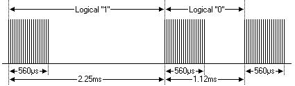
The NEC protocol uses pulse distance encoding of the bits. Each pulse is a 560µs long 38kHz carrier burst (about 21 cycles). A logical “1” takes 2.25ms to transmit, while a logical “0” is only half of that, being 1.125ms. The recommended carrier duty-cycle is 1/4 or 1/3 .
Protocol
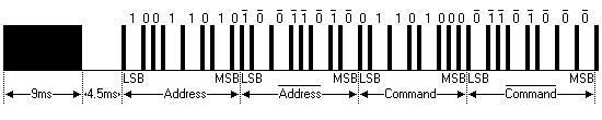
The picture above shows a typical pulse train of the NEC protocol. With this protocol the LSB is transmitted first. In this case Address $59 and Command $16 is transmitted. A message is started by a 9ms AGC burst, which was used to set the gain of the earlier IR receivers. This AGC burst is then followed by a 4.5ms space, which is then followed by the Address and Command. Address and Command are transmitted twice. The second time all bits are inverted and can be used for verification of the received message. The total transmission time is constant because every bit is repeated with its inverted length. If you’re not interested in this reliability you can ignore the inverted values, or you can expand the Address and Command to 16 bits each!
Keep in mind that one extra 560µs burst has to follow at the end of the message in order to be able to determine the value of the last bit.
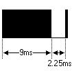
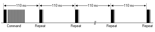
A command is transmitted only once, even when the key on the remote control remains pressed. Every 110ms a repeat code is transmitted for as long as the key remains down. This repeat code is simply a 9ms AGC pulse followed by a 2.25ms space and a 560µs burst.
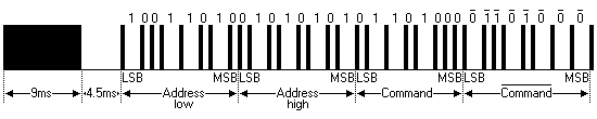
Extended NEC protocol
The NEC protocol is so widely used that soon all possible addresses were used up. By sacrificing the address redundancy the address range was extended from 256 possible values to approximately 65000 different values. This way the address range was extended from 8 bits to 16 bits without changing any other property of the protocol.
By extending the address range this way the total message time is no longer constant. It now depends on the total number of 1’s and 0’s in the message. If you want to keep the total message time constant you’ll have to make sure the number 1’s in the address field is 8 (it automatically means that the number of 0’s is also 8). This will reduce the maximum number of different addresses to just about 13000.
The command redundancy is still preserved. Therefore each address can still handle 256 different commands.
Keep in mind that 256 address values of the extended protocol are invalid because they are in fact normal NEC protocol addresses. Whenever the low byte is the exact inverse of the high byte it is not a valid extended address.
(4)Test Code:
The IR receiver on the PCB board is controlled by IO port(D12) of the Arduino Nano board.

(5)Test Result:
Upload the test code to the Arduino Nano board, power up with a USB cable, open the serial monitor to click and
set to 9600.
Press a key on the IR remote control, you will view a code on the serial monitor. If FFFFFFFF shows up, just ignore it.

Code of each key.
Project 10.2: IR Remote Control Car
(1)Description:
In the above experiment, we have learned about the knowledge of the 8*8 dot matrix display, the motor driver and speed regulation, the infrared receiver and the infrared remote control. In this experiment, we will use the infrared remote control and the infrared receiver to control the car.
(2)Components Required:
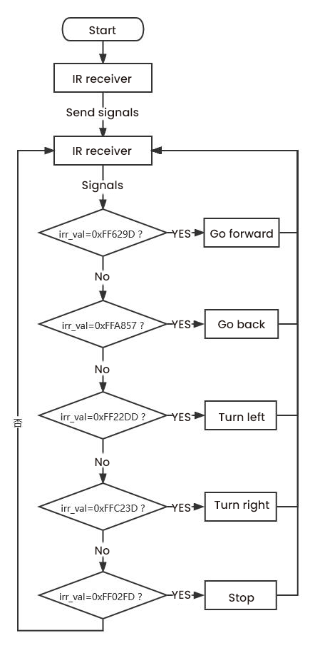
(3)Working Principle:
Keys |
Keys Code |
Functions |
|---|---|---|
|
FF629D |
Go forward |
|
FFA857 |
Go back |
|
FF22DD |
Turn left |
|
FFC23D |
Turn right |
|
FF02FD |
stop |


(4)Flow Chart:
(5)Test Code

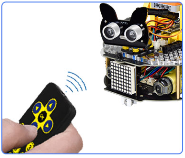
(6)Test Result:
Upload the test code to the Arduino Nano motherboard, install batteries, turn the power switch to the ON end, power up and press a key of the IR remote control. Then the car will make the corresponding movement.
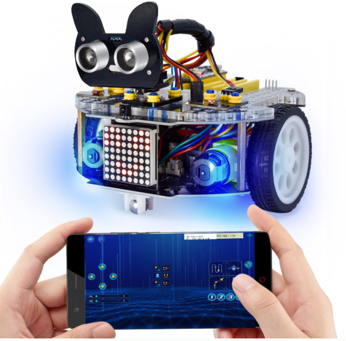
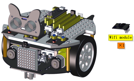
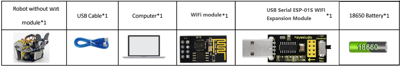
Project 11: WIFI Control
In this lesson, we control the car through app. The Beetlebot APP sends commanders to the WIFI ESP-01 module then transfers to it to the microcontroller. By doing this, the car can perform different functions.
Project 11.1: WIFI Test
(1)Description:
The ESP8266 serial WiFi ESP-01 module is an ultra-low-power UART-WiFi transparent transmission module and designed for mobile devices and IoT applications.
It can achieve networking functions by connecting devices to Wifi internet.
(2)Components Required:
(3)Knowledge:
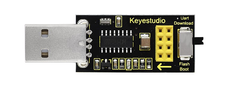
USB to ESP-01S WiFi module serial shield:
It is suitable for the ESP-01S WiFi module. Turn the DIP switch on the USB to ESP-01S WiFi module serial Expansion Boardto Flash Boot, and plug into computer’s USB port. You can use serial debugging tool to test the AT command.
Turn the DIP switch on the USB to ESP-01S WiFi module serial expansion board to the UartDownload, ESP-01 module is at download mode. You can download the firmware to ESP-01 module using AT firmware.

ESP8266 serial WIFI ESP-01:
ESP8266 serial WiFi ESP-01 is an ultra-low-power UART-WiFi transparent transmission module. It can be widely used in smart grids, intelligent transportation, smart furniture, handheld devices, industrial control and other fields.
Features
Support wireless 802.11 b/g/n standards
Support STA/AP/STA+AP three modes of operation
Built-in TCP/IP protocol stack to support multi-channel TCP Client connections
Supports many Socket AT commands
Supports UART / GPIO data communication interface
Supports Smart Link smart networking function
Supports remote firmware upgrades(OTA)
Built-in 32-bit MCU, can also be used as an application processor
Ultra-low-power and highly integrated Wi-Fi chip for battery-powered applications
Working temperature range: -40℃ to + 125℃
3.3V single power supply
(4)Functions
A. Main functions
The main functions that can be achieved by ESP8266 include: serial port transparent transmission , PWM regulation, GPIO control.
※Serial port transparent transmission: The transmission is reliable with a maximum transmission rate of 460800bps.
※PWM regulation: Adjusting lights and tricolor LED, motor speed control, etc.
※GPIO control: Control switch, relay, etc.
Working modes
The ESP8266 module supports three operating modes, STA/AP/STA+AP.
❊STA mode: The ESP8266 module can access to the Internet through a router, so the mobile phone or computer can remotely control the device through the Internet.

❊AP mode: ESP8266 module, as a hotspot, allows the direct communication with the module and cellphones/computers, achieving wireless control of the local area network (LAN).
❊STA+AP mode: two modes coexist, that is, the Internet can achieve free switch.

(5)Applications
Serial CH340 to Wi-Fi
Industrial transparent transmission DTU
Wi-Fi remote monitoring/control
Toy industry
Color LED control
Integrated management of fire protection and security intelligence.
Smart card terminals, wireless POS machines, Wi-Fi cameras, handheld devices,etc.
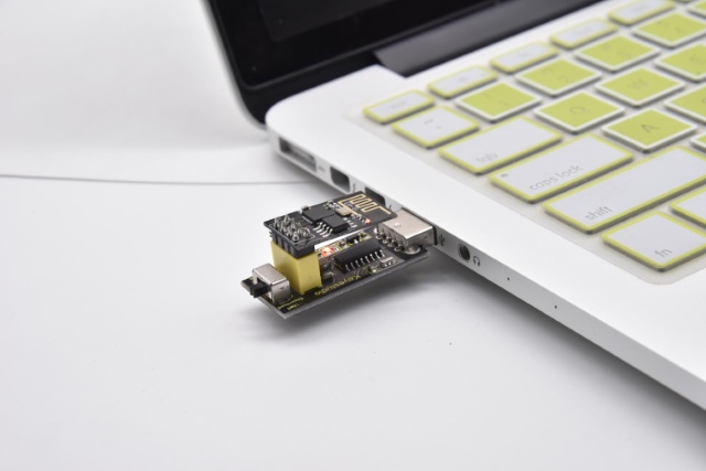
(6)Insert the Wifi serial port expansion board into the USB port of your PC
Insert the ESP8266 serial WIFI ESP-01 module into the USB to ESP-01S WIFI expansion board.

Turn the DIP switch of the USB to ESP-01S WIF expansion board to UartDownload end and plug it to the USB port of your computer.
(7)APP:
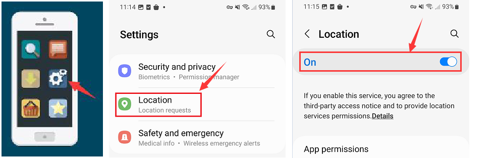
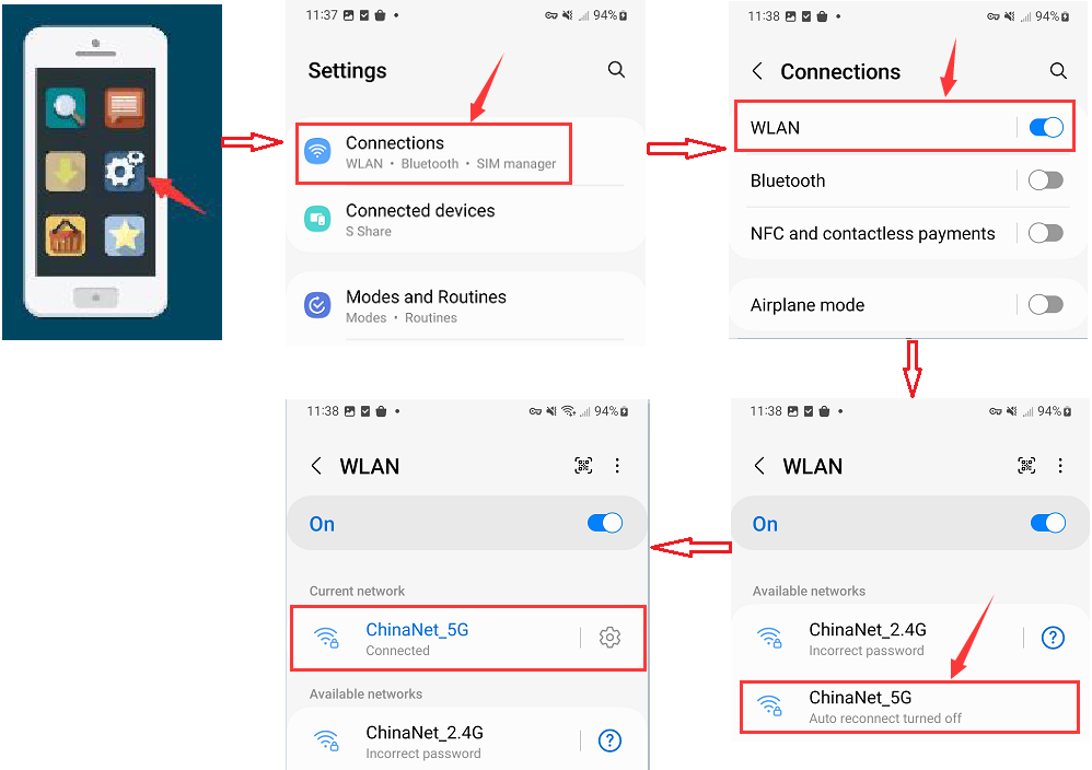
For Android system:
(1). Turn on the location services of the mobile phone and connect the wifi of yourself.
(2). Search Beetlebot in Google Play, or open the following link to download and install the app.
https://play.google.com/store/apps/details?id=com.keyestudio.beetlecar
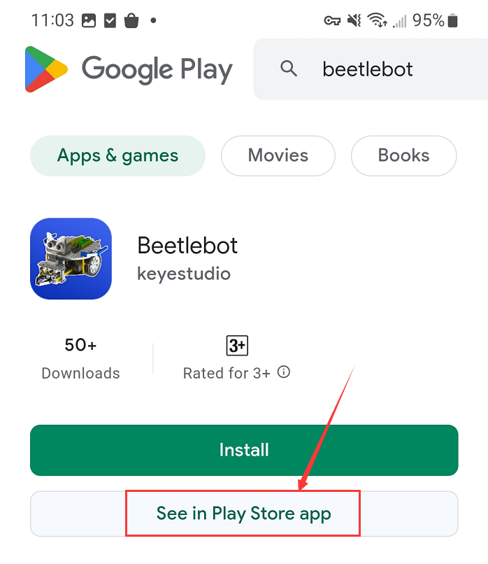

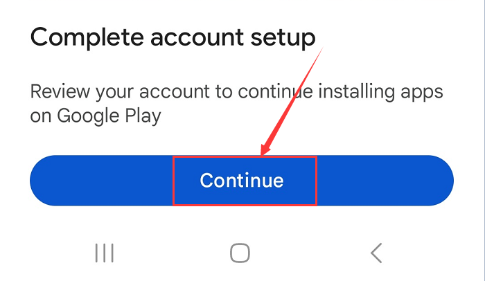
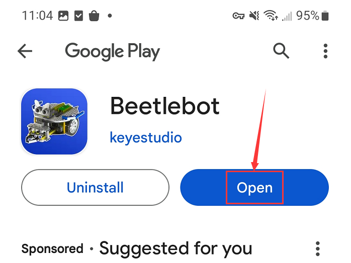
(3). Click Open button and enter interface of the app.
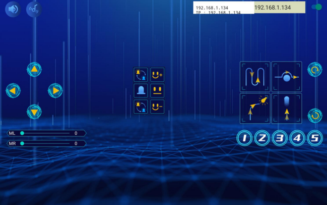
(4). Input the detected Wifi IP address(for example, the IP address in the serial monitor is 192.168.1.134), and Slide the button  to the right to connect Wifi. At same time, the IP address will be shown at the left box, which means that Wifi is connected well.
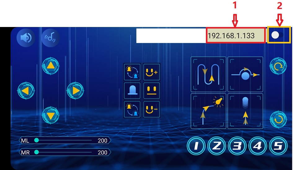
Note: Click buttons on the APP, the blue indicator on the ESP8266 serial WIFI ESP-01 module will flash, indicating that the APP has been connected to WIFI.
For IOS system
(1). Turn on the location services of the mobile phone and connect the wifi of yourself.
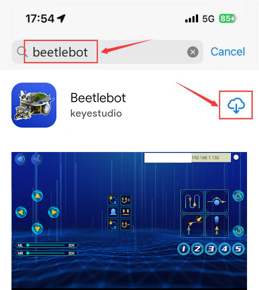
(2). Open App Store

(3). Search Beetlebot in App Store,click“ ”to download Beetlebot APP.
(4). Click Open button and enter interface of the app.
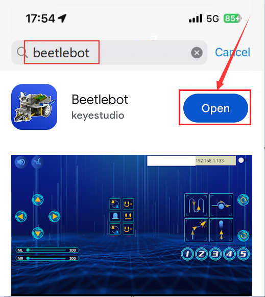
(5). Input the detected Wifi IP address(for example, the IP address in the serial monitor is 192.168.1.134), and Slide the button to the right to connect Wifi. At same time, the IP address will be shown at the left box, which means that Wifi is connected well.
Note: Click buttons on the APP, the blue indicator on the ESP8266 serial WIFI ESP-01 module will flash, indicating that the APP has been connected to WIFI.
(8)Add the ESP8266 control board:
Click to enter the main page, select the control board needed. In this project, we select the Plus board and click Connect.
Then it is connected, Click Go to Editor to return the code editor. Icon will change into  and will change into
  . This means the Plus board is connected to the COM port.


If the ESP8266 board is connected , but icon doesn’t change into  . You need to click to connect the COM port. Click and Connect.
Then you will find a page pop up, showing Connected.


(9)Add the Beetlebot wifi module:
Click to enter sensor/module expansion interface and click“Beetlebot wifi”, “Not loaded”will switch into“loaded”. Then the Beetlebot wifi module will be added.
Click to return the code editor, then you will view the Beetlebot wifi module.


(10)ESP8266 Code:
If there is no wifi in your home, just enable your shared wifi on the phone.

Note:You need to change the wifi name and password into yours.

After the Wifi name and Wifi password are changed, plug the USB to ESP-01S WIFI expansion board to the USB port of the computer, turn its DIP switch to the “Uart Download” end and click “Upload” .
Upload the ESP8266 code to the ESP8266 to WIFI ESP-01 module.
Note: if the code is uploaded successfully, reboot the ESP-01S WIFI expansion board.

After the code is uploaded. Unplug the USB to ESP-01S WIFI expansion board and ESP8266 serial WIFI ESP-01 module.
(11)Interface the Arduino Nano board

(12)Set the interface of Beetlebot:
Open KidsBlock to clickto enter the main page. Select Beetlebot,and click Connect,then the Beetlebot is connected.
Click“Go to Editor” to return code editor, will change into,and into; this indicates the device is connected to the port.
Then click to switch mode. The will change into
(13)Arduino Nano Test Code:

(14)Test Result:
Click Upload to upload the test code to the Arduino Nano board.
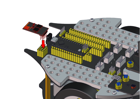
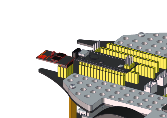
Then insert the ESP8266 serial WIFI ESP-01module into the WiFi port of the PCB board.
(Note:keep the USB cable connected.)

Click  and set baud rate to 9600. Then the serial monitor will show your IP address of Wifi.
The IP address of Wifi sometimes changes. If the original doesn’t change, check the IP address of Wifi again.
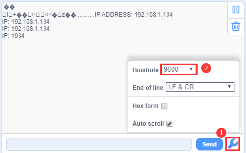
Input the detected Wifi IP address(for example, the IP address in the serial monitor is 192.168.1.134), and Slide the button to the right to connect Wifi. At same time, the IP address will be shown at the left box, which means that Wifi is connected well.
Note: Click buttons on the APP, the blue indicator on the ESP8266 serial WIFI ESP-01 module will flash, indicating that the APP has been connected to WIFI.
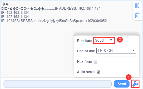
After the APP has connected to the WIFI, start the following operations:
Click buttons on the app, the serial monitor will print some control characters, as shown below.
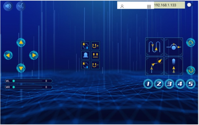
Interface of App
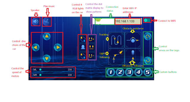

Click ,a“smile”pattern will be displayed;click
  ,“十”will be shown;click
 ,“❤”will be shown.
Project 11.2: Multi-purpose Car
(1)Description:
In this project we will demonstrate multiple functions of the Beetlebot car through app.
(2)Components Required:
(3)Test Code:
The code of ESP8266wifi module is not changed, then change the wifi password of the code into yours.

(4)APP operation, as shown below:
Note: See the previous lesson of Project 11.1 for how to connect your app to WiFi。
Click to control the car to move in different directions ;
click
to control the car to move in different directions ;
click  to control the SK6812RGB to show different colors;
click
to control the SK6812RGB to show different colors;
click  to control the 8*8 dot matrix display show different patterns.